What is Hybrid SCD?
Slowly Changing Dimension (SCD) Type 6 is also called as “Hybrid SCD” that combines three fundamental SCD techniques. Type 6 can be used when you want to maintain complete history and would also like to have an easy way to manage current version.
The point of “type 6” or “Hybrid” processing is that your track changes by adding a new row for each new version but then you update some of the attributes on previous versions to reflect the current state of data. That way the data can be filtered and rolled-up across all versions for reporting purposes.
SCD Type 6 is a combination of type 1 + type 2 + type 3
- Type 1 – The data gets overwritten for all the history records i.e., Past values are not preserved
- Type 2 – Creating new rows to capture changes using Flag, Version and Date ranges
- Type 3 – Adding attributes to the previous record
Type 6 is built on the type 2 technique by also adding current attributes in the dimension so that fact rows can be filtered or grouped by either the type 2 value or the attribute’s current value.
When to use SCD6?
- When we want to maintain historical attributes, and also supporting the ability to report historical performance data according to current attribute values
- To understand the historical facts based on the current attribute values, we will filter or summarize on the current attributes
Implementation of Hybrid SCD Step by Step process:
Staging table:
In our Staging table, we have all the columns that are required to map for the dimension table involved in mapping. The structure of the staging table as below:

NOTE:
- The Staging table will have only current data / one day data
- All the output ports required for dimension table is there in the staging table
- EMPNO is the primary key in the staging table
Dimension table:
Structure of the dimension table as below:

NOTE:
- SEQ is the surrogate key
- EMPNO is the unique record identifier
- Record versions are maintained using the time range, STARTDATE and ENDDATE
- Active record will have ENDDATE as ‘9999-12-31’ and Current_Flag as “Y”
Now, we know the staging table and dimension table we are going to use, we can start implementing the design in the mapping designer.
Step 1: Drag and Drop one instance of source and four instances of target on to the mapping designer.
Step 2: Drag and drop Lookup transformation
- Perform lookup on your target table
- Drag and drop EMPNO from Source Qualifier to Lookup
- In the Condition tab, add a new condition as below, EMPNO = EMPNO1
- Set Lookup Policy on Multiple Match in Properties Tab = Use Last Value. As like the screen shots below,


Step 3: Create Expression transformation
Drag and Drop EMPNO, EMPNAME, DESGN, CITY from Lookup to Expression and all the ports/columns from Source Qualifier

In the Expression transformation, I have created a new port FLAG_FLTR to filter based on No Change as ‘N’, Update as ‘U’ and Insert as ‘I’
The expression given for the new port (FLAG_FLTR), as shown in the below screen

NOTE: For better understanding, I have suffixed “_TGT” for all ports coming from Lookup.
Step 4: Create Router transformation
Drag and Drop all the output ports from the expression to Router. In Router we need to create two groups
Update_Insert as FLAG_FLTR = ‘U’ Insert as FLAG_FLTR = ‘I’

Step 5: Create four Expression transformations
In the first Expression transformation, Drag and Drop the output ports from Router transformation having Group Name “Update_Insert” to the first expression “Exp_Upd”. Update ENDDATE and Current_flag in this expression
The Expression given for the Port Name, ENDDATE = TO_CHAR(ADD_TO_DATE(SYSDATE,’D’,-1),’YYYY-MM-DD’) – to get the enddate updated for the non-active record based on current_flag.
For the Port, CURRENT_FLAG, map the value ‘N’ in the expression as shown below


The Future of Big Data
With some guidance, you can craft a data platform that is right for your organization’s needs and gets the most return from your data capital.

Step 5a: Create Update Strategy transformation
Drag and Drop the output ports to the update strategy from the expression “EXP_UPD” Set Update Strategy expression = DD_UPDATE

Step 5b: Drag and Drop the output ports from the Update strategy “UPDSTGY_UPD_FLAG_ENDDATE” to the first target instance “Tgt_EMP_DIM_UPD”
In this target instance (Tgt_EMP_DIM_UPD), we will update ENDDATE and CURRENT_FLAG based on SEQ,

The SQL query for Update override as in the screen shot below,

Step 6: In the Second Expression transformation
Drag and Drop the output ports from Router transformation having Group Name “Update_Insert” to the second expression “Exp_INS_Upd”.
- In this expression we are comparing the EMPNO, if it matches we are passing the DESGN value or else NULL for the port name “PREV_DESGN3”.
- Hard coded the Current_flag as “Y” as the screen shot below,

Step 6a: Drag and Drop the output ports to the second target instance (Tgt_EMP_DIM_INS_UPD_RCRD) from the second expression transformation (EXP_INS_Upd)
But, for the Port Name “SEQ”, it is a Surrogate key – we will generate the sequence using Sequence Generator transformation
Step 6b: Create Sequence Generator transformation
NOTE: No need to change any default properties
Drag and Drop the NEXTVAL output port from SEQTRANS and map that to SEQ column in the second target instance (Tgt_EMP_DIM_INS_UPD_RCRD) as like the below screen shot,

Step 7: In the third Expression transformation
Drag and Drop the output ports from Router transformation having Group Name “Insert” to the third expression (Exp_INS). This is a direct insert coming from the before data or source data

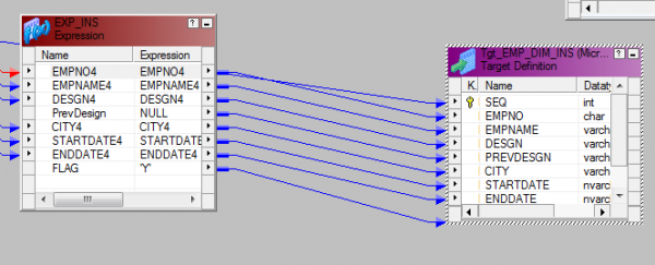
Step 7a: Drag and Drop the output ports from third expression transformation (EXP_INS) to the third target instance (Tgt_EMP_DIM_INS). But, for the SEQ column in the target instance we will get the port from Sequence Generator which was already created (SEQTRANS).
- We will map NEXTVAL from Sequence Generator transformation to the SEQ column in the third target instance (Tgt_EMP_DIM_INS)

Step 8: In the fourth Expression transformation
Drag and Drop the output ports from Router transformation having Group Name “Update_Insert” to the fourth expression (Exp_UPD_DESGN). Here we are updating all the records DESGN column in the target as the current DESGN to all the records in the fourth target instance.
- Created a New Port called CURRENT_DESGN and given the expression as – CURRENT_DESGN: IIF(EMPNO2=EMPNO11,DESGN2,NULL)

Step 8a: Create Router transformation – To filter the records which are NOTNULL for the port (CURRENT_DESGN)
Drag and Drop the EMPNO and CURRENT_DESGN output ports from the expression to Router and here we are filtering the records
DESGN_FLTR: ISNULL(Current_Desgn)
Step 8b: Create Update Strategy transformation
Drag and Drop the output ports from Router transformation to update strategy to update the EMPNO and DESGN from the DEFAULT group
Set Update Strategy expression = DD_UPDATE

Step 8c: Drag and Drop the output ports from the fourth expression transformation (EXP_UPD_DESGN) to the fourth target instance (Tgt_EMP_DIM_UPD_DESGN)
In the properties tab, Set update override: UPDATE INTF.EMP_DIM SET DESGN = :TU.DESGN WHERE EMPNO = :TU.EMPNO. we are updating all the records related to DESGN based on the EMPNO for the DESGN column in the target table

We have completed the mapping development and below is the structure of the completed mapping.

Step 9: Create a workflow for the same mapping and Run the mapping..!!!
Now, let’s see how the Data is going to be in the database.
- Source Data

- Initial load to the target EMP_DIM

- SRC After data

- Output of Incremental load to the target EMP_DIM

- SCD Type 2 – Creating a new additional record. In this methodology all history of dimension changes is kept in the database. You capture attribute change by adding a new row with a new surrogate key to the dimension table that we can capture by having versioning’s like STARTDATE,ENDDATE and CURRENT_FLAG in the below screen shot
- SCD Type 3 – Adding a new column. In this type usually only the current and previous value of dimension is kept in the database. In the below screen shot , the highlighted yellow color column denotes the type 3 implementation

Hope you would have gained information on SCD Type 6 and how to implement in Informatica. Try it out and let me know your comments. Will see you soon with my next blog..,